Appearance
Positioning GPS Projects
The quality of your GPR data and results is only as good as the positioning method used to collect the data. Often, poor planning on grid layouts result in very clear data being unusable once back in the office.
In general, there are two types of GPR projects: those that are positioned using a grid of some sort (one-directional, two directional, etc) and those that are positioned using a tracking system such as GPS or a total station in a freeform path, which itself could be in a grid pattern. The distinction is that grid surveys rely on a wheel odometer for distance and positioning and GPS surveys rely on a GPS or total station of positioning.
GPR profiles collected with even the most accurate RTK GNSS receivers require some processing of the positioning data to ensure accuracy. Data collected with standard GPS receivers can contain many other sources of error which can be addressed in Geolitix. Sources of GNSS errors include loss of satellite coverage, poor satellite geometry and multipathing in under vegetation, loss of RTK correction signal, latency issues and the positioning offset between the center of the GPR antenna or array and the center of the GNSS antenna.
It is important to note that nothing done within Geolitix cannot be undone at any time. Even upon completion of the project, if a mistake is noted, you can easily go back to the positioning tab of the GPR layer to change something and that change will propagate throughout the rest of the processing and interpretation steps automatically.
INFO
When displaying array GPR data only the track of the GPS antenna is shown. This is considered as the “spine” of the survey path and can be edited in the same way as a single channel GPR survey. This is done to simplify track editing.
Importing GPS or total station projects
When importing GPS tracked profiles, the associated GPS log file from the radar controller must be uploaded at the same time as the radar data. Ensure that the corresponding files types are uploaded with your radar profiles. For more information on what files are needed check Import files.
Note that some formats including SEGY and ReflexW files contain GPS positioning data within the radar data files.
Applying processes to GPS tracks
Individual processing steps can be added from the processing panel. These processes can be applied globally to all profiles in the project, or to specific GPR files. As an example, GPR files collected near trees may contain poor RTK GNSS points due to multipathing. Processes can be applied only to those GPR files to eliminate poor GPS points as needed. Use the  on the left side bar to add a new process to the GPS tracks.
Duplicate GNSS time stamps
Some GNSS receivers output positioning information at greater than 1 Hz, but generate NMEA timestamps with integer values. Thus, there are a series of repeated timestamps with the same time code, which can cause distortion in the GPR data. Users can select how these duplicate time stamps are addressed on the platform.
Discard bad GPS points
Large skips in GPS points are likely caused by loss of WAAS or RTK signal or a change in satellites being tracked. These offsets must be removed before the GPR profile can be processed.
For each of these skips, the GPS has travelled an unrealistic distance between points. We have a number of possibilities that we can choose from depending on the source of the problem.
Discard by distance All skips in the GPS track which are beyond the threshold value will be filtered.
Discard by HDOP value The geometry of satellites, atmospheric conditions, and most importantly nearby objects (buildings, trees, etc. can block signals or cause multipathing) can reduce the quality of a GNSS signal. HDOP is one measure of the accuracy of the GNSS solution. A lower number means a high degree of accuracy. Using this process Geolitix will filter poor GNSS accuracy based on the selected HDOP threshold.
Discard by number of satellites The number of satellites in view has a significant impact on GNSS accuracy. You can specify the minimum number of satellites for each GNSS point. Points recorded with fewer than the minimum number are discarded.
Discard by GPR fix type. NMEA GGA sentences recorded by most GPR systems include the type of GNSS fix. GPS tracks can be filtered based on a required fix type. For example, only RTK-fix points can be kept while any point without an RTK would be discarded.
Smoothing GPS tracks
Jagged GPR tracks can be smoothed using the Smooth locations processing step. Moving the slider shows the effects of the function on the map.
Odometer-GNSS Fusion
When the radar is triggered by a wheel odometer as well as tracked by GNSS, the odometer records how far the unit has travelled between fixes. This process fuses that distance information with the GNSS track to distribute the positioning points more evenly along the path, improving spatial accuracy. At least three GPS positions are required.
Geolitix combines the odometer tick increments with the along-track distance measured by the GNSS, enforces a monotonically increasing distance, splits the track where there are jumps in position, and re-renders the corrected points along the original GNSS path. The correction is along-track only — points are not shifted laterally.
- Maximum correction — the largest along-track correction allowed for any single point, entered in the project distance unit (step 0.1). A value of 0 or an empty field applies no clamp.
Swap X-Y coordinates
If the positioning was logged with its X and Y coordinates transposed during acquisition, this process swaps them back. It has no parameters.
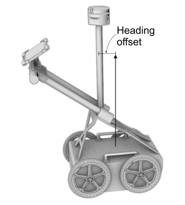
Offset corrections
GPS antennas are rarely situated directly atop the exact center of a GPR antenna. There can be multiple types of offsets which must be accounted for when positioning radar data.
- Heading offset. The heading offset is the distance between the center of the GPR antenna and the center of the GPS antenna. The heading offset follows the route taken and places the GPR data along an interpolated curve. This is particularly important for low frequency GPR systems where the offset between the GPS and the GPR may be many metres.
- Lateral offset. The lateral offset is most used with array GPR systems where the GPS receiver may be placed to one side of the center of the array "spine". The offset is positive to the right of the radar centerline in the direction of travel.

- X and Y offsets. In some scenarios, a GPR survey most be shifted in the Y or X directions to match a local grid or other survey layout.
- Time lag offset (latency). Latency is a critical consideration when using any GPS tracking, regardless of the published accuracy of the receiver and the frequency of the data output. Even L1/L2 RTK GNSS receivers at 10 Hz exhibit some latency between the time the position fix is made and the attaching of that position to a GPS trace. Although this latency is usually only fractions of a second, even a 0.3 second latency at walking speed would offset measurements of targets by 30 cm. This problem is much more serious when towing a radar at 100 km/hr, where a small latency could mean metres of offset.
When using GPS a recommended calibration procedure is to survey a large figure "8" whose center passes over a strong reflector like a metal plate or manhole cover. In Geolitix, you can find the latency value to converge the reflections to a single point.
The comparison shows a pipe mapped with an L1/L2 RTK GNSS with NMEA output at 10 Hz with no latency correction (top) and with a latency of 0.4 seconds (bottom).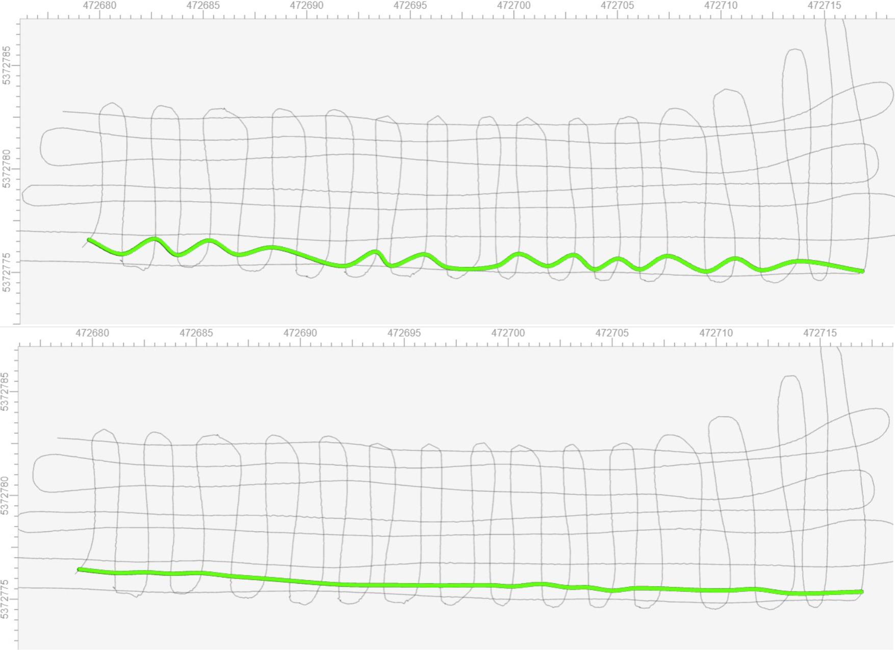
Editing GPS tracks manually
Any GPR track can be manually edited by first selecting the track to be edited, which highlights it. The pencil icon  at the top of the screen can then be selected to enable manual point editing.
Holding the SHIFT key will allow you to select multiple points. You can also select a rectangular area of points to move or delete. Select the check mark icon to confirm your moves and deletions.
The GPR profile shown below has issues with positioning accuracy due to poor GNSS coverage and dense vegetation. Using the mouse wheel to zoom into the track, we see that there are issues with this GPR track where the radar was snagged on rough terrain and was pulled back and forth.
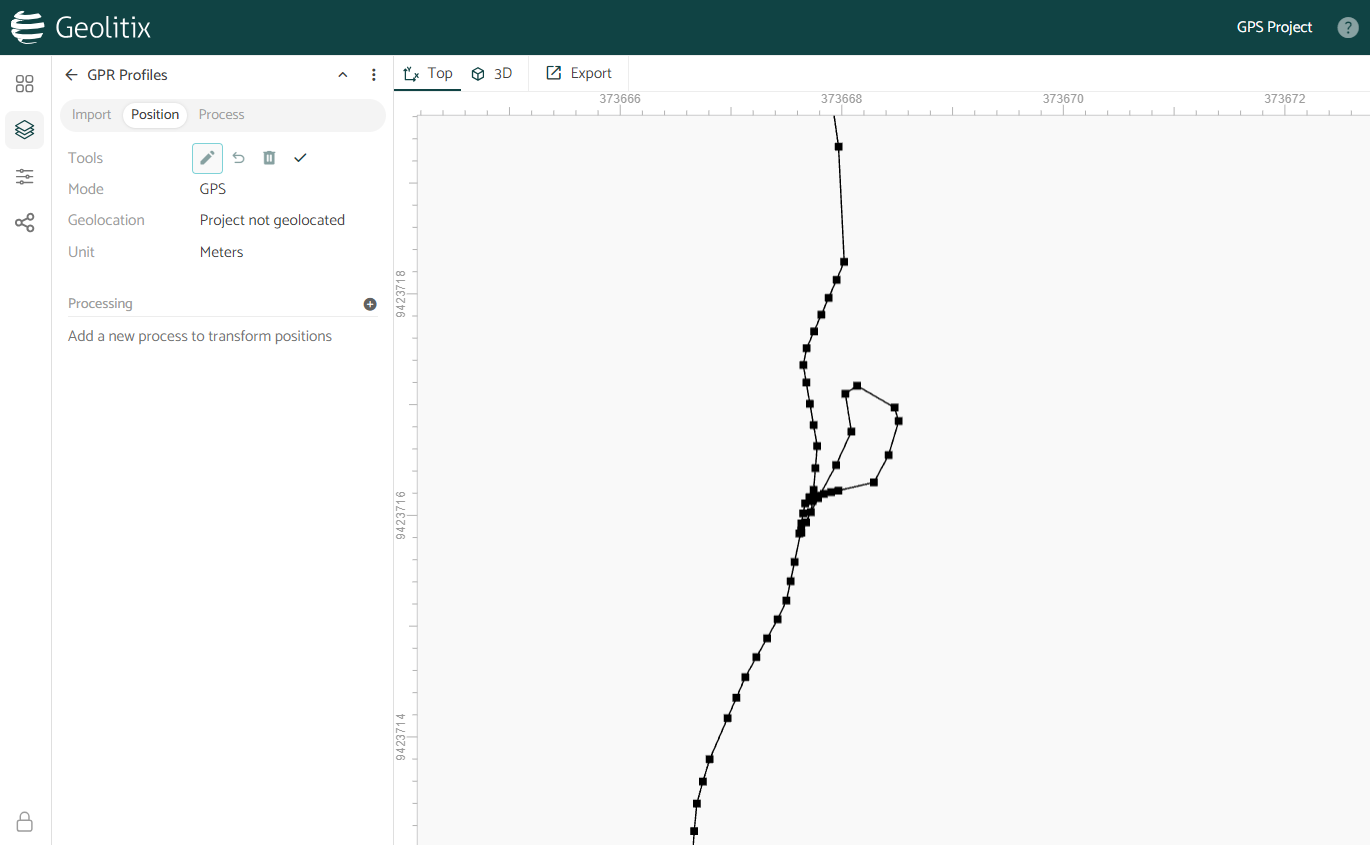
Individual points may then be moved or deleted from the track.
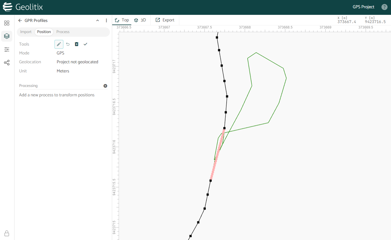
- Black points have not been modified
- Red points denote selected points
- Green points have been manually modified by you
- Greyed out points have been deleted
To undo changes you can select the desired points, and then click the undo button.
Combining, splitting, and reversing profiles
Sometimes we need to re-orient, discard sections or combine profiles.
- To reverse a profile, select it by clicking on it, and click the Reverse icon beside Tools.
- To split a profile, move the cursor to the point where the profile is to be split and right-click the mouse. Select the Split option.
- To combine profiles, hold the SHIFT key and select two profiles, then click the Combine icon beside Tools.

Splitting and re-orienting continuous grids
Often, surveys are collected as continuous grids with accurate GPS tracking. This is commonly done with drone GPR surveys.
Sometimes it is desired to split such a long profile to simplify navigating through each profile to track pipes or other linear targets. Splitting such zig-zag surveys can be done automatically.
- Step 1: Select the profile you wish to split and re-orient.
- Step 2: Click the Split zigzag pattern icon at the top of the map.
In the example shown below, a grid collected with a drone GPR, was split using the automatic Split zigzag pattern tool. The split lines now all start in the south (green) and end in the north (red).